5.3L Engine Rebuild Page 27
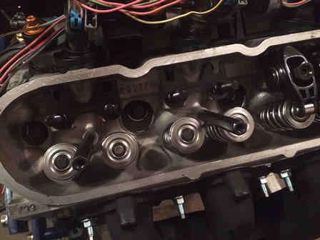
Figure 105. Install the long coupling nuts on the studs. These will keep the valve cover from being tightened down to far and squeezing out the gasket.

Figure 106. The last step of the valve cover install is to install the screws with the supplied sealing washers. The screws will probably be replaced with ones painted copper later, after the valve covers are also painted. The next step for the valve covers is to install the coil brackets.
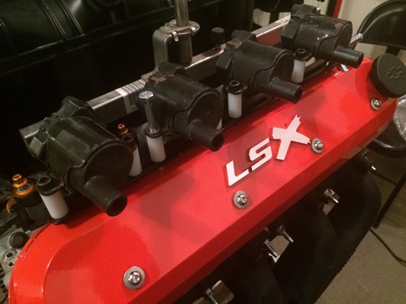

Figure 107. The Proform website says that their Proform 69520 Coil Bracket Kit does not work with the D585 truck coils. Well, this proves that to
not be the case. You just do not use the included coil angle brackets, and bolt the coils directly to the valve cover mount using
spacers. This photo is proof of concept, and final installation will be with black-anodized aluminum spacers instead of the
plastic ones used here. They are 1/4 inch ID by 1 inch long spacers. 3/4 inch long spacers would work also. The only modification
that has to be done is drill the coil bolt holes out from 5mm to 6mm.
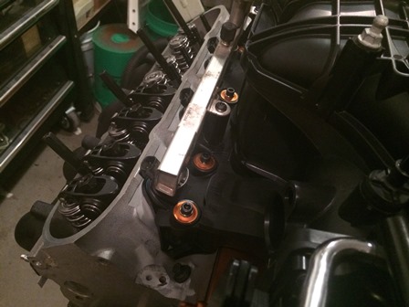
Figure 108. Completed final installation of the intake manifold. Decided to ditch the hex head bolts and used black socket heads with the stock spacers, which are painted copper. Follow the factory torque sequence, and torque them down in two steps. First step is 44 inch lbs, and second step is 89 inch lbs. The black socket heads with the copper spacers really looks good with the black manifold, a nice splash of color. The socket head screws are M6 x 70mm.
| Pages: 1, 2, 3, 4, 5, 6, 7, 8, 9, 10, 11, 12, 13, 14, 15, 16, 17, 18, 19, 20, 21, 22, 23, 24, 25, 26, 27, 28, 29, 30, 31, 32, 33, 34, 35, 36, 37, 38, 39 |
| <--Previous | 5.3L Engind Build Home | Next--> |
| Contact: Copperhead | As an Amazon Associate I earn from qualifying purchases | © 2019 |