Tearing Down the CJ7
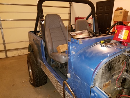
Figure 1. Started tearing down the front end and tub. In this photo, the windshield, doors and hood have been removed. The bolts used on the hood hinges and the windshield frame hinges are torx flat head bolts. These bolts in the plainest language just suck. When everything is reassembled, they will be replaced with hex socket head screws. The torx screws round out far too easily and become a real pain to remove. Not one of Jeep's brighter ideas.
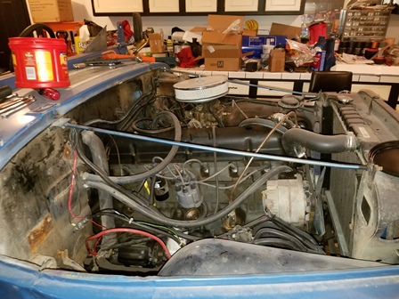
Figure 2. The hood has been removed. There were two bolts in each hinge holding it to the cowl.
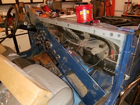
Figure 3. Started pulling the dash off. It had the horrible torx head bolts. Fortunately, they all came out. they will be replaced with hex button head screws. The wiring was a rats nest and has obviously been hacked together at some time in the past. Pulling this off also shows that this jeep was originaly purple, and not blue.
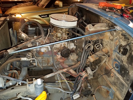
Figure 4. Both fenders are now off. They came off pretty easily, compared to the dash and other items.
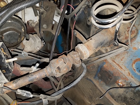
Figure 5. Prepariing to pull the steering column out. Loosen the clamp on the spline for the column and thoroughly spray it with penetrating oil or pb blaster. It will not come out easily, if it has been on there a long time. Disconnect the shifter linkage on an automatic equipped jeep as shown here.
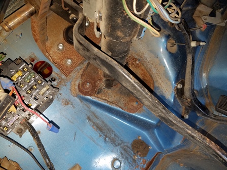
Figure 6. Remove the nuts holding the column/firewall covers on, then remove the cover halves. These are pretty rusty, if new are available, they will be replaced.
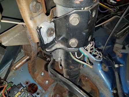
Figure 7. To Remove the steering column, disconnect the linkage, then remove the bolt that is on each side of the bracket shown in this photo. the steering column will then drop down. If you previously sprayed the coupling on the shaft on the engine side of the firewall, a couple good sharp tugs should free it, then you can pull the steering column out of the tub.
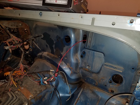
Figure 8. Here all the heater box assemblies have been removed. We got in too much of a hurry to remove the upper vent tube, and used a prybar and cracked the tube. This piece is no longer made, and is not a cheap piece at a salvage yard. We should have heated up the seal so it would come loose without excessive prying. An expensive mistake. One note here, we are not going to use the original wiring harness, so for ease of disassembly, we cut the wires instead of disconnecting them. This harness is really not that complicated, but we will purchase a pre-made unit when the time comes.
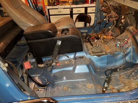
Figure 9. Started removing the seats and seat belts. The seats came out fairly easily. The seat belts are held on with the torx head bolts from the devil. Some of them came out, others did not. For us, it was not worth fighting the ones that did not come out and the belt held by them will remain with the tub when it is removed.
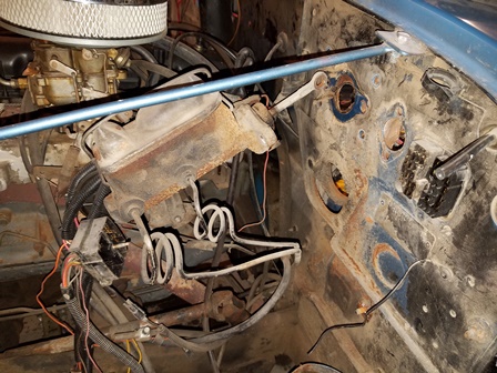
Figure 10. The master cylinder was removed, along with the pedal assembly. Both the brake pedal assembly and the emergency brake pedal assembly are heavily rusted. If replacements can be located, they will be changed out. The emergency brake cable is also in very bad shape.
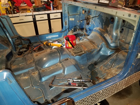
Figure 11. The front half is not completely stripped and ready. The pictures truly do not show how badly rusted this tub is. It is far worse than it appears in these photos.
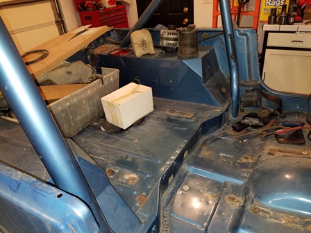
Figure 12. The back half is now stripped and ready. The roll bar is held in with the demon (sarcasm) torx head screws, and several rounded attempting to get them out. We will replace the roll bar with a roll cage kit later on, it will be safer than this roll bar so although it may cost quite a bit to do, it will be well worth it, and there will be no more torx head screws to deal with.
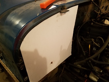
Figure 13. Here is a piece of poster board purchased from Officemax to use as a template for the heater system holes and openings. It was trimmed to fit the curve of the cowl lip, and when it is placed on the fiberglass tub firewall, will give me the correct locations to cut the holes out.
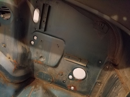
Figure 14. The other side of the firewall with the poster board up against it. Take a marker or pencil or whatever you have and mark the poster board with the openings. Do the same thing with the openings for the defroster, and for the cowl fresh air intake. Do your cowl intake opening with the poster board on the inside. The reason for this is that fiberglass tub will be thicker than the steel tub, and you will need to offset the opening towards the back to accomodate that distance. If you butt the poster board against the inside of the firewall and cut your opening from there, you will be the correct distance back. Without doing this, you could be as much as 1/2 inch too far forward for the opening to be positioned properly for the duct that bolts up to it.
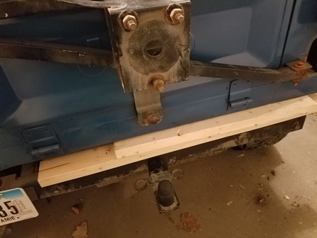
Figure 15. The body is now lifted up off the frame approximately 4 inches. 2 x 4's were placed under it as stand offs until it can be lifted off completely. This added clearance gave more room to unbolt the gas tank roll over check valves that are bolted up behind the rear driver side fender. The rear tire carrier is rusted out and is going to the junkyard with the body.
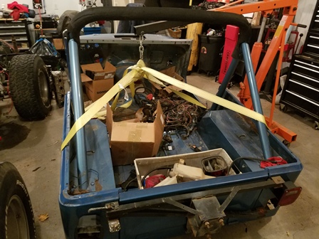
Figure 16. The body lifted off the frame. We used two 2200lb twenty foot long recovery straps to lift it. As you can see, the roll bar and rear tire carrier are going with the body. They are rusted and heavily damaged. The roll bar will be replaced with a roll cage later. Lifting it like this made it very rear heavy, and required adjusting the lift point accordingly to get it to balance. The lifting unit is the Harbor Freight 2 ton folding crane. It lifted it easily with no problems at all.
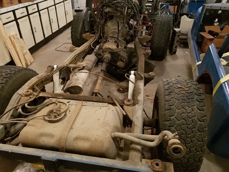
Figure 17. The frame with the body off. Everything except the springs, axles, and front steering are going to be removed from the frame to prepare it for the blasting shop. All the brake lines, fuel lines, e-brake cables are all going to be removed. The brake and fuel lines will be replaced anyway as they are old and rusty and we do not trust them with the new set up. The e-brake is going to be removed from the rear axle and relocated to the transfer case output, so that will require a new cable set up.
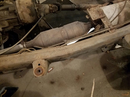
Figure 18. The body bushings were so rusty they had to be driven out with a screwdriver and a hammer. The frame body mounts themselves are fine with no real discernable rust or other damage to them. Unusual for a CJ7 from the Midwest.
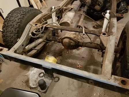
Figure 19. The gas tank has now been removed from the frame. We used a hydraulic scissor lift cart from Harbor Freight to support it while it was being unbolted. There are three bolts on the front crossmember and four on the rear crossmember. As you can also see in the photo, this Jeep has the rare 1986 dana 44 rear end. Another big plus discovered is that the rear axle has also been converted to the 2-1/2 inch YJ springs. They are 2-1/2 inch lift BDS Suspension springs.
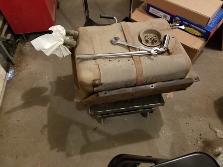
Figure 20. The old gas tank sitting on the lift cart. There was quite a bit more gas still in it than was expected, and it will need to be removed before the gas tank can be disposed of. This one is a 15 gallon unit, and will be replaced with an oem 20 gallon unit. Rags were stuffed in the larger openings to keep the workshop from smelling of gasoline, until it gets pumped out into a suitable container. We will not be re-using the skid for this tank, and it will be disposed of as well.
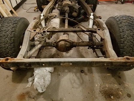
Figure 21. The rear crossmember bumper/cover has been removed and the rear crossmember is now exposed. This is another rust-prone area for the CJ7. This one is solid with no discernable damage except a little surface rust. This project has a very solid foundation to build this project on.
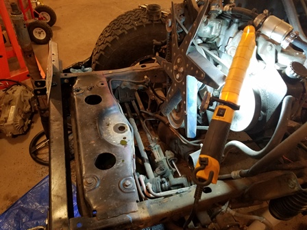
Figure 22. Drained the radiator of coolant and transmission fluid, then took out the single bolt holding the grill on the frame and removed both the radiator and grill.
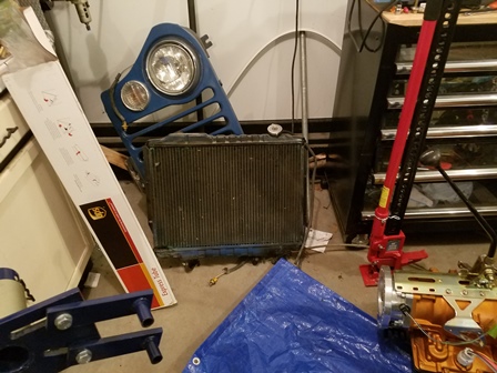
Figure 23. Took out the 4 bolts holding the radiator on the grill and removed it. Set them both aside for later.
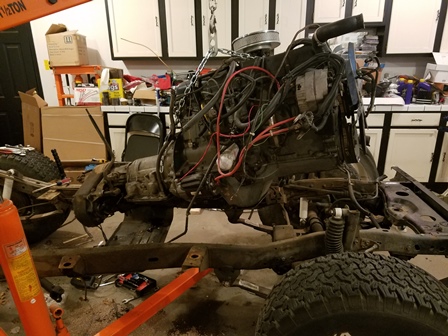
Figure 24. Removed the two nuts on the engine mounts with an 11/16 socket. Removed the three nuts holding the transmission mount holding it to the belly skid with an 11/16 socket. Lifted the engine, transmission, and transfer case out as a single unit. Here it is suspended in the air with the crane hoist.
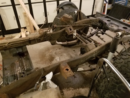
Figure 25. The frame empty of the engine and transmission. Now all the brake and fuel lines will be removed, as well as the engine mounts. The engine mounts will be replaced with the Novak LS engine mounts after the frame as been sandblasted. Every bracket that can be unbolted from the frame will be removed prior to taking in to be cleaned up.
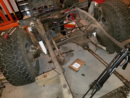
Figure 26. All the brake lines are now removed, and the drivers side motor mount has been taken off.
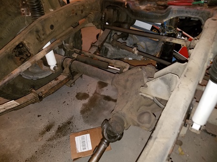
Figure 27. The passenger side motor mount has now been removed. In the photo you can see a bracket on the frame that has a bump stop mounted on it for the axle. When installing the new engine mounts, this bracket will have to be removed. It is welded on and will need to be cut off with a saw or plasma cutter.
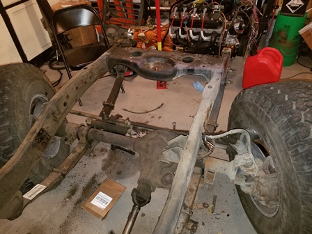
Figure 28. The front bumper has been taken off, along with the shock towers, and the steering gear. The sway bar and brackets was also removed. When removing the sway bar brackets, the rear bolt on the bottom of both brackets broke off in the frame. Not sure at this time what method we are going to use to get them out. We will avoid drilling a hole to get at the weld nuts as much as possible, but it might come to that to get the bolts out and replace the fastener in the frame. We would like to drill it out and use a rivet nut, but it all depends on how easy it will drill.
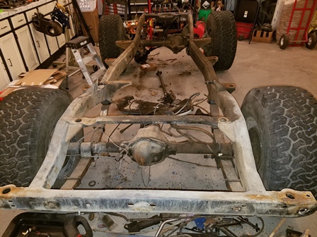
Figure 29. View from the rear looking towards the front. The frame is now completely stripped and ready to go to the sand blaster. The blasting company requested us to leave the axles on it so they can move it around easier.
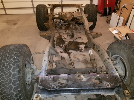
Figure 30. The stripped frame looking from the front to the rear. We have another small pile of parts that will be scrapped because they are not going to be reused, such as the factory skid plate, gas tank, driveshafts, and bumpstops.
Disclaimer: The information provided here is how I did it. I strongly urge you to do your own research and make sure you do it right. No claim is made that the information provided is the only way it should be done, or that you should follow my work without verifying for yourself that it is correct. You are free to do as you choose with the information shared here, but you do so at your own risk.
