Frame Work
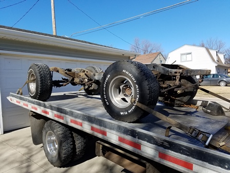
Figure 1. The frame is on the car hauler to go to the sandblasting shop. It was taken to Keystone Stripping in Omaha. Much thanks to John's Towing in Council Bluffs, IA for transporting the chassis. It should be back soon and ready to clean and paint. At this point, we can say that the teardown phase is complete, and now it is time to start putting it all back together.
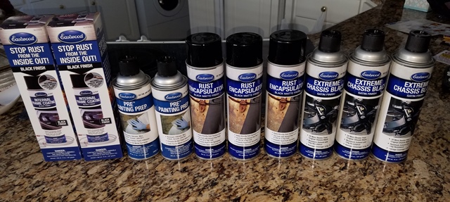
Figure 2. The paint for the chassis is here. You may be wondering why we are not going to powdercoat the frame. There is one reason: rust. If we damage the powdercoating and rust gets up underneath it, we cannot fix it without stripping the whole frame down again. With the paint system, we can fix any scuff areas that need it without tearing the frame down. From left to right here are the Eastwood products that were selected: Internal Frame Coating Black, Pre Paint prep, Rust Encapsulator Black, and Extreme Chassis Black Satin. The only thing missing from this photo is After Blast, it is on back order, and will hopefully be here before the frame comes back.
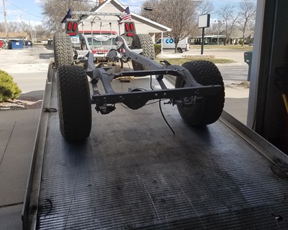
Figure 3. The chassis has returned from sandblasting. They did very nice work, not a lot of debris in the frame rails, and the metal is very clean.
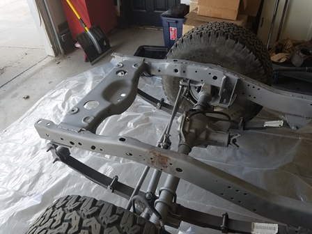
Figure 4. Here is a shot of the front of the frame. You can see a spot they could not get one hundred percent clean during the blasting, on the driver side frame rail. This spot is where the factory shock mount bolts to the frame. The way it is designed, it traps debris and moisture against the frame, causing the damage you see here.
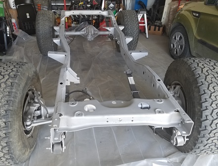
Figure 5. In this image, some damage that was not noticed until now is visible. On the passenger side frame rail, the frame is pushed in about two and a half inches right at the front body mount. This was not good news. This will have to be fixed. We could buy a replacement frame, but then we would have to have it blasted, and it would cost as much to ship as the repair will cost. We are going to opt for having the frame straightened at a local body shop.
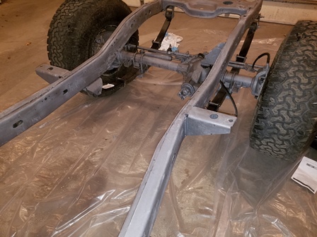
Figure 6. It is hard to tell the difference, but the frame here has been coated with Eastwood After Blast, this was done to keep it from rusting. The frame has turned from a whitish gray to a darker gray with the coating. We will not paint it now until the frame has been straightened.
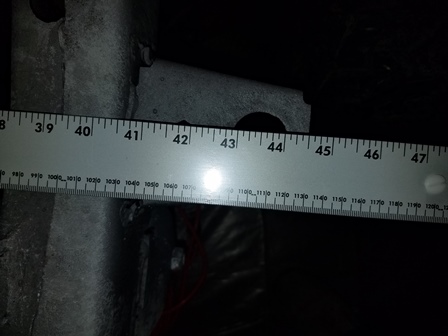
Figure 7. The measurement across the frame for the rear six body mounts is 43.5 inches. As seen here, the frame across this section is not bent and is where it is supposed to be. No straightening required here.
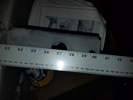
Figure 8. The measurment across the frame for the front body mount is supposed to be 37.84 inches. As you can see, it is now at 37. The passenger side rail will need to be pulled out 0.84 inches to bring it back into alignment with the rest of the frame.
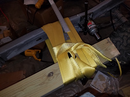
Figure 9. Setting up to do the pull. A 6x6 wood beam is used, and the strap is a 3 inch 30ft long recovery strap wound around the beam and frame as many times as possible. The 12 ton jacks are position at points where the frame is not bent. The straight edge rule is placed so we can see how much the frame is moving as the jacks are pumped up. The jacks are 12 ton cheapos bought from Harbor Freight.
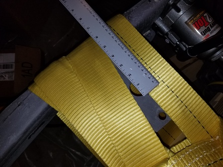
Figure 10. The frame moved approximately 1/16 of an inch with every stroke of the jack once the straps tightened up. It was pulled 3/8 of an inch past the point where we wanted it to be, as the metal will spring back that distance once the pressure is taken off of it. When done, it was where it needed to be.
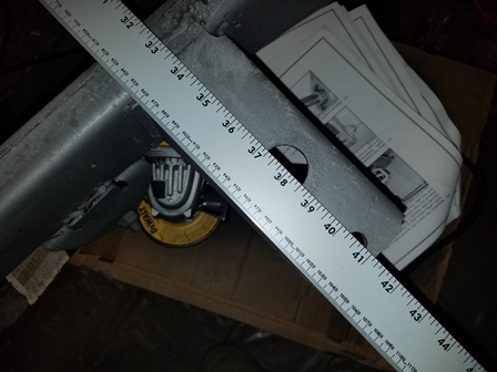

Figure 11. Now the frame is back into alignment. Is it perfect? No, but it certainly is close enough to get the bolts in, and the jeep will now track
straight down the road. The drawback now is that a softball sized divot is in the inner passenger side rail. This is because of the stretch of the metal
when it was originally bent the first time. This will be a weak point in the frame. It will be addressed by welding a 3/16 x 6inch reinforcement plate over it.
We will also attach a M.O.R.E. FP300 Frame Reinforcing Plate to the opposite side, and tie them together with a third plate underneath the frame.
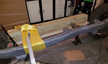
Figure 12. One last look at the beam set up before moving on with the build. This did cost a little due to buying the beam and the jacks, etc., but it is still a fraction of the cost of having it done on a frame machine at a body shop. The cost to have it professionally done was close to what it cost to buy a good used replacement, and doing it myself, saved all that money. One word of caution, there is a lot of pressure built up during a pull like this, and if something had snapped, someone could have very easily gotten hurt. The 6x6 beam was probably overkill, but it is still cheap insurance against someone getting hurt. Make sure if you do something like this that you have taken into account how many pounds of force you are gointg to be utilizing and adjust your equipment accordingly so it does not break.
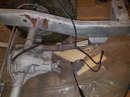
Figure 13. The differential bumpstop that was welded to the frame had to be removed for the Novak motor mount to bolt up properly. A reciprocating saw was used to cut it off flush with the frame, then a large hammer knocked the remaining bottom plate off.
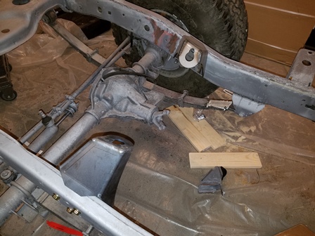
Figure 14. Here the Novak Conversions motor mounts loosely bolted on for a trial fit. We did not use the hardware that came with them to bolt to the frame, as they did not seem very stout, they also will not be long enough after the reinforcing plates are added. New hardware was ordered from McMaster-Carr. They are 3/8-24 x 3inch grade 8 flange bolts, along with 3/8-24 grade 8 nylock flange nuts.
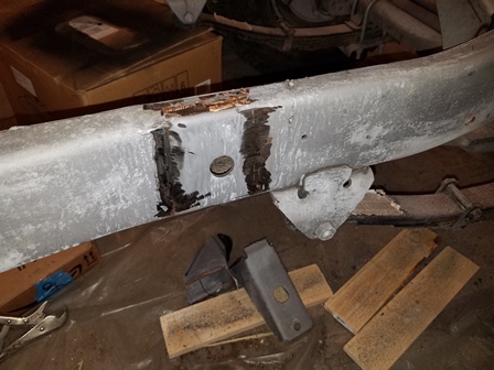
Figure 15. The passenger side front body mount has been removed. The end of the reinforcing plate will cover this area, then the body mount will be welded back on. On this side of the fiberglass body, the hole for the mount is further back, so the body mount has to be moved anyway.
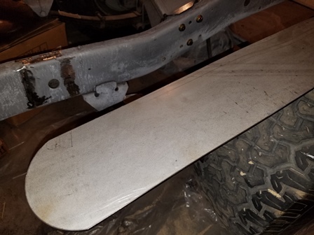
Figure 16. The shackle hanger welded to the frame causes a fit issue with the reinforcing plate. A notch will have to be put in it to clear so it will fit up against the frame rail.
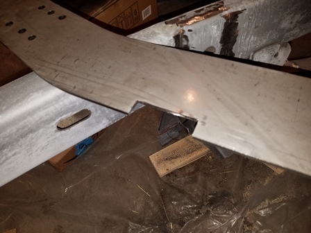
Figure 17. The plate is now notched to clear the shackle hanger. The plate for the other side will need to be notched for clearance also.
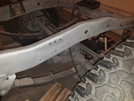

Figure 18. The frame and the plate are coated with 3M 05917 Weld-Thru Coating II - 12.75 oz. on their mating surfaces, to keep rust from attacking
them once they are welded together.
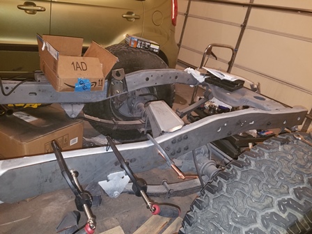
Figure 18. The plate is clamped on and welding begins. Starting at the rear end of the plate, it will be done with a 2 inch weld, skipping 2 inches, then welding 2 more inches, and so on, until it is welded all the way around.
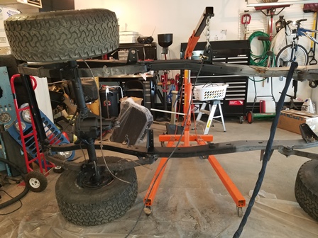
Figure 19. The easy way to paint the bottom of the frame. It is being painted with Eastwood Rust Encapsulator. The reinforcing plate was also welded on at the point where the frame was bent. While you cannot see it in this image, the frame metal is horrible to weld, it seems to have no end of contamination in it that causes the puddle to outgas causing holes in the bead. A real challenge.
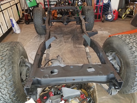
Figure 20. The frame is now completed with the first coat of paint. The Rust Encapsulator will cure for 24 hours, then will be top-coated with Eastwood Satin Extreme Chassis Black paint. The front differential will not be painted as it will be eventually be replaced down the road with a much stronger Dana 44 unit.
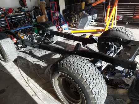
Figure 21. The frame has now been topcoated with Eastwood Extreme Chassis Satin Black, and it has also been treated with Eastwood Internal Frame Coating Black. No images of the internal frame coating were taken, you cannot see much anyway through the small holes of the frame. This should take care of 99 percent of any future rust issues on the frame by preventing them from occurring in the first place. By doing this instead of powdercoating, if the frame gets scratch on the trail, it is easily fixed by re-applying the Rust Encapsulator and the Extreme Chassis Black.
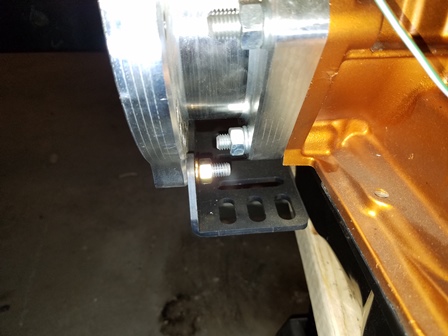
Figure 22. We are now going to install the GenRight Offroad Universal Crossmember. To begin we tightened up the mounting bracket that came with the Novak Conversion Kit. The urethane transmission mount bolts to this bracket.
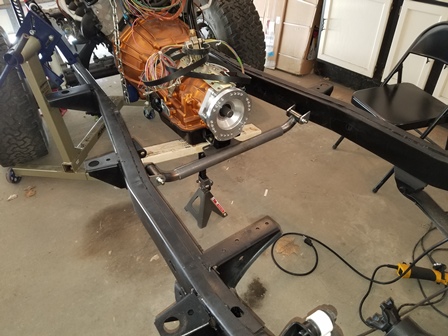
Figure 23. The mount plate has been welded to the center section and the crossmember is being test fit. Each side has a short tab and a long tab that will be welded to the frame. During fitting, we discovered that due to the angle of the jeep frame rail, the long tab is approximately an eighth of an inch too short. While we could have ground an eighth off of the short tab to adjust for that, we felt that would bring the bushing closer to the frame than we would like, so we are having new longer tabs made for the long side instead. When those are done, they will be welded to the frame and the rest of the crossmember will be welded up and completed.
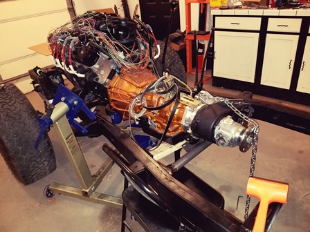
Figure 24. Test fitting the transfer case and the crossmember. Clearance is very tight, might require a couple spacers between the transmission mount and the crossmember. the crossmember is as far down in the frame as it can go.
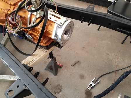
Figure 25. The crossmember tabs are now final welded, and the frame repainted. They look real nice.
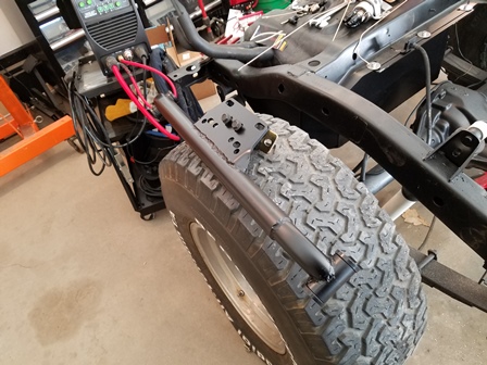
Figure 26. The crossmember is now finish welded, and painted, ready to install. It was painted with Eastwood Rust Encapsulator as the base coat, then Extreme Chassis Black Satin as the top coat.
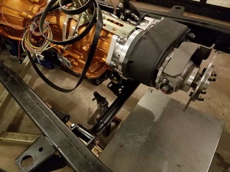
Figure 27. The crossmember is now installed. With the transfer case clocked flat, there was a clearance problem between the case and the crossmember, the case was resting on the crossmember on the passenger side. This will have to be corrected, as there needs to be room for movement of drivetrain assembly.
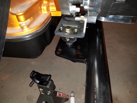
Figure 28. The solution was to add extra thick washers as spacers between the transmission mount and the crossmember plate. The original mount used one bolt, (It had provision for three.) Holes were drilled in the mount plate for the two outer bolts. Two extra-thick washers per bolt were installed between the plate and mount, raising it up approximately 3/8 of an inch.
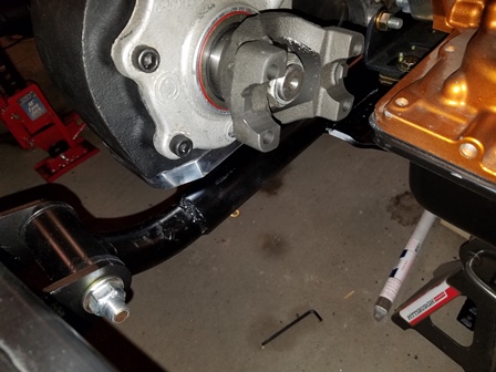
Figure 29. You can see in the photo that we now have approximately 1/4 inch of clearance for the transfer case, which gives plenty of room for movement with no danger of crashing into the crossmember. The front yoke is a 1310. We wanted a 1350, but it will not clear the transmission.
Disclaimer: The information provided here is how I did it. I strongly urge you to do your own research and make sure you do it right. No claim is made that the information provided is the only way it should be done, or that you should follow my work without verifying for yourself that it is correct. You are free to do as you choose with the information shared here, but you do so at your own risk.
